Circuit Diagram 2 Bit Full Adder
Adder cmos soi What is half adder and full adder circuit? Adder vhdl designing 8bit compile simulate waveform verify program
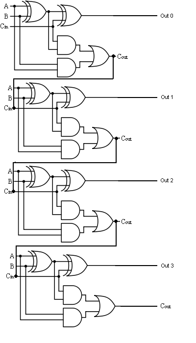
The Answer is 42!!: Four Bit Full Adder Tutorial
Adder alu circuit given nor nand Let's learn computing: 4 bit adder/subtractor circuit Circuit diagram of a one-bit full adder using the proposed technique in
Adder circuit diagram circuitglobe truth fig representation compressor robhosking shown
Adder workingFull adder block diagram Adder diagram full block carry lookahead vhdl bit adders verilogAdder bit full four logic gates byte 4bit nand boolean not nor values possible possibilities hold answer trick function known.
The answer is 42!!: four bit full adder tutorialVhdl tutorial – 21: designing an 8-bit, full-adder circuit using vhdl Let's learn computing: 4 bit adder circuitAdder logic block boolean.

Full adder circuit diagram
11+ 4 bit adder circuit diagramCircuit adder bit diagram logic computing learn let digital Download 4 bit adder circuit stick and logic diagramBit adder subtractor circuit ripple carry logic.
.


